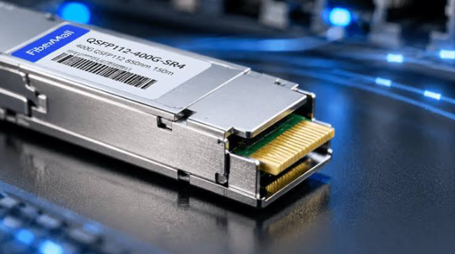
Deploying 400G connectivity in an NVIDIA AI cluster is not a matter of choosing one “400G module” and applying it uniformly. The link has two distinct ends, and NVIDIA has deliberately separated the physical interfaces: the adapter or DPU side uses QSFP112, while the switch side uses OSFP. Understanding this asymmetry is the single most important planning step, because a module that fits one cage will not fit the other, even when both are rated for 400G.
The QSFP112–OSFP Split: Why the Same Speed Uses Different Cages
A 400G QSFP112 module carries four electrical lanes, each running at roughly 100 Gbps PAM4, for an aggregate host interface of 400GAUI-4. An OSFP module on the switch side uses a larger package with a different lane arrangement and its own integrated thermal design. The QSFP112 shell is flat-topped and relies on the host cage’s riding heatsink for cooling; the OSFP shell is typically finned and manages heat within the module itself.
This mechanical and thermal divergence is not an optical limitation. The optical engines inside a QSFP112 SR4 and an OSFP SR4 may be closely related, but the host interface and the cage geometry are not interchangeable. A QSFP112 module cannot be inserted into an NVIDIA Quantum-2 or Spectrum-4 switch port, and no passive QSFP112-to-OSFP adapter is supported. The practical rule is simple: match the module form factor to the cage, not to the speed label.
See also: How to Balance Mom Life and Lifestyle: Tips for Maintaining Peace, Style, and Health
400G QSFP112 Module Types: SR4, DR4, and NVIDIA Part Numbers
Within the QSFP112 family, the optical interface determines reach and fiber type, not the form factor alone. The two most common 400G QSFP112 variants for adapter-side deployment are SR4 for multimode short reach and DR4 for single-mode moderate reach.
A 400G SR4 QSFP112 module uses four parallel multimode lanes at 850 nm through a single MPO-12/APC connector. Typical reach is 50 meters over OM4 fiber, and power consumption sits in the 8–10 W range for four active channels. The generic industry designation Q112-400G-SR4 follows the QSFP112 MSA and IEEE 400GBASE-SR4 electrical and optical specifications, with OM4 reach commonly rated at 50–100 meters depending on the implementation and FEC configuration.
NVIDIA’s own adapter-side SR4 part is the MMA1Z00-NS400. It is a single-port QSFP112 multimode transceiver with a flat-top shell, 850 nm VCSEL optics, and an MPO-12/APC interface. NVIDIA specifies 30 meters over OM3 and 50 meters over OM4, with a maximum power draw of about 9 W when all four 100G-PAM4 channels are active. The module supports both InfiniBand and Ethernet, and firmware automatically selects the protocol based on the attached switch. It is intended for ConnectX-7 QSFP112 adapters and BlueField-3 QSFP112 DPUs.
The single-mode counterpart is the MMS1X00-NS400, a QSFP112 DR4 module using 1310 nm optics and an MPO-12/APC connector for reaches up to 500 meters over single-mode fiber. The distinction matters: SR4 and DR4 are not interchangeable at the optical level, and a QSFP112 SR4 cannot communicate with a DR4 module simply by changing the patch cable.
Two Deployment Patterns: Straight 400G and Split 200G
NVIDIA AI fabrics typically place a twin-port 2×400G OSFP module in the switch and fan out to QSFP112 adapters. In the straightforward pattern, two independent fiber pairs connect the switch’s twin-port OSFP to two separate ConnectX-7 or BlueField-3 QSFP112 interfaces, delivering a dedicated 400G link to each endpoint. This is the layout used when maximum per-node bandwidth is the priority.
The second pattern uses a 1:2 splitter fiber assembly on the switch side to serve four 200G endpoints. Only two of the four lanes in the QSFP112 module activate, and the module’s power draw drops from roughly 8.5 W to about 5.5 W—a meaningful reduction in a dense rack where 400G to every node would be overprovisioned. The trade-off is that both optical paths from the twin-port switch module must use the same cable configuration: straight with straight, or splitter with splitter. Mixing one straight leg with one splitter leg on the same twin-port module can produce lane-mapping errors or intermittent link instability.
Legacy Contrast, Common Failures, and the 10G Reference Point
It is useful to keep the QSFP112 transition in perspective by recalling the previous generation of short-reach optics. A 10G SR SFP+ module operates over duplex LC multimode fiber at 850 nm, with typical reach of 300 meters over OM3 and 400 meters over OM4, and power consumption well under 1 W. The broader 10G SFP+ category also includes single-mode and extended-reach variants, but the SR version remains the standard short-reach building block for 10G enterprise and data center links. The jump from 10G SR SFP+ to 400G SR4 QSFP112 is not merely a speed increase; it is a shift from duplex serial optics to four-lane parallel optics, from LC to MPO connectors, and from sub-watt modules to 8–10 W devices that depend on host-assisted cooling.
That thermal and mechanical dependence explains several common QSFP112 deployment failures. A module that registers but passes no traffic often indicates a straight-versus-splitter mismatch on a twin-port switch link. A module that will not seat with normal resistance usually means the wrong part family was ordered—an MMA part for an adapter cage when an MMS switch-side part was needed, or vice versa. A link that never comes up at any speed may point to a lane-rate mismatch: QSFP112 uses four 100G PAM4 electrical lanes, while a QSFP-DD 400G port uses eight 50G PAM4 lanes, and a passive copper assembly cannot bridge those architectures. Firmware and CMIS compatibility should be verified before hardware is replaced, because older network operating system or adapter firmware versions can misidentify otherwise functional optics.
The working conclusion for NVIDIA 400G AI fabrics is to treat QSFP112 as an adapter-side and DPU-side form factor, select SR4 or DR4 according to fiber infrastructure, and verify the exact cage type and part-number prefix before ordering. The switch side will be OSFP; the adapter side will be QSFP112; and the two meet through validated optical links rather than mechanical adapters.