Have you ever struggled with timing circuits that require multiple components, or found yourself frustrated when trying to trigger SCRs reliably in your electronics projects? These common challenges often lead hobbyists down a rabbit hole of complex designs and bulky component lists. Enter the UJT transistor—a unique electronic component that simplifies oscillator and timing circuits while reducing your parts count significantly. Unlike conventional transistors, the Unijunction Transistor offers a specialized solution for pulse generation and triggering applications that would otherwise demand intricate arrangements of resistors, capacitors, and multiple active devices. But why should you choose a UJT over more familiar options like NPN transistors or Power MOSFETs? The answer lies in its elegant simplicity and cost-effectiveness for specific applications. This article will guide you through the fundamentals of UJT transistors, compare them with other transistor types to help you make informed choices, explore practical projects where they shine, and provide essential tips for purchasing quality electronic components from reliable sources. Whether you’re building your first relaxation oscillator or looking to streamline existing designs, understanding UJTs will expand your electronics toolkit considerably.
Understanding UJT Transistors: Basics and Operation
What is a UJT? Core Definition and Structure
The Unijunction Transistor is a three-terminal semiconductor device with a fundamentally different architecture from conventional bipolar transistors. Its structure consists of a lightly doped n-type silicon bar with heavily doped p-type material forming the emitter junction near the center. The two ends of the silicon bar connect to Base 1 (B1) and Base 2 (B2), while the emitter (E) forms the third terminal. This construction creates what engineers call an intrinsic standoff ratio, typically ranging from 0.5 to 0.8, which determines the voltage at which the device triggers. The standoff ratio remains relatively constant for a given UJT model, making circuit behavior predictable. Peak point voltage, another critical specification, indicates the emitter voltage needed to initiate conduction—usually between 10 to 20 volts for common electronic components. Unlike three-layer bipolar transistors, the UJT’s simple bar structure with a single junction makes it inherently suited for switching rather than amplification, reducing manufacturing complexity and cost for hobbyists.
How Does a UJT Work? Operation Principles
The UJT operates through a fascinating negative resistance characteristic that makes it ideal for timing applications. When voltage applies across B2 and B1 with the emitter initially at low potential, the device remains off and presents high resistance. As emitter voltage increases and reaches the peak point—determined by the supply voltage multiplied by the intrinsic standoff ratio—the emitter junction becomes forward-biased. At this trigger moment, resistance between the emitter and B1 suddenly drops, allowing current to flow freely in what resembles an avalanche effect. This rapid transition from high to low resistance creates a sharp pulse at B1, perfect for triggering other circuits. The device remains conducting until emitter current falls below a minimum holding value, after which it resets to the off state. In relaxation oscillators, this behavior combines with an RC timing network: a capacitor charges through a resistor until reaching the peak point voltage, the UJT discharges it rapidly, then the cycle repeats. This self-oscillating property eliminates the need for multiple transistors or complex feedback networks, making UJTs exceptionally efficient for pulse generation, sawtooth waveform creation, and SCR triggering circuits where simplicity and reliability matter most to project builders.
Comparing UJT with Other Transistors: NPN and Power MOSFETs
UJT vs. NPN Transistors: Key Differences
While both UJTs and NPN transistors are semiconductor devices, their operational philosophies diverge dramatically. NPN transistors feature three layers forming two junctions, designed primarily for amplification and general-purpose switching with continuous control over collector current through base current. They excel in linear applications where signal gain matters, such as audio amplifiers or voltage regulators. The UJT transistor, conversely, has one junction and functions purely as a threshold-triggered switch with no amplification capability. Its negative resistance region makes it self-triggering once the emitter voltage crosses the peak point, eliminating the need for external timing components that NPN circuits would require. For hobbyists building a simple LED flasher, an NPN approach demands additional transistors or integrated circuits to create oscillation, whereas a UJT accomplishes this with just a resistor and capacitor. The UJT’s intrinsic standoff ratio provides built-in voltage reference, removing the need for precise biasing networks that NPN designs often require. When your project needs amplification or analog signal processing, NPN transistors remain the clear choice. But for timing circuits, pulse generation, or SCR triggering where simplicity reduces failure points, the UJT’s specialized design offers unmatched elegance and cost savings.
UJT vs. Power MOSFETs: Application Scenarios
Power MOSFETs like the IRFPG50 operate in an entirely different realm than UJTs, handling high currents and voltages for applications such as motor drives, power supplies, and switching regulators. These voltage-controlled devices offer extremely low on-resistance and fast switching speeds, making them ideal when controlling hundreds of watts. The IRFPG50, for instance, manages substantial power loads that would instantly destroy a UJT rated for milliamps. However, this capability comes with complexity—MOSFETs require gate drive circuits, heat sinking considerations, and protection networks that increase both cost and board space. A UJT cannot replace a MOSFET in power applications, but it excels at triggering them. In phase-controlled circuits, a UJT relaxation oscillator generates precise timing pulses that fire the gates of MOSFETs or thyristors, combining the UJT’s simple oscillation with the MOSFET’s power handling. For hobbyists, this means using a UJT costs pennies and requires minimal supporting components for control functions, while reserving expensive power MOSFETs strictly for the heavy lifting. If your project involves switching loads under 50mA at low voltages, a UJT alone suffices. For motor control or high-current switching, pair a UJT timing circuit with appropriate power MOSFETs to leverage each component’s strengths effectively.
Practical Applications for Hobbyists: Solving Project Needs
Common Hobbyist Projects Using UJT Transistors
UJT transistors shine in projects where simplicity and reliability trump complexity. Relaxation oscillators represent the most common application, converting DC voltage into repetitive pulses for LED flashers, metronomes, or alarm circuits. A basic UJT oscillator requires only a resistor, capacitor, and the transistor itself—far fewer components than equivalent NPN designs. Tone generators for electronic music experiments benefit from the UJT’s ability to produce sawtooth waveforms naturally, creating distinctive buzzing sounds when driving a speaker through an audio transformer. SCR and triac triggering circuits for AC power control rely on UJTs to generate precise firing pulses, enabling dimmer switches or motor speed controllers without microcontrollers. The device’s predictable triggering voltage makes it ideal for voltage-sensing applications, where circuits need to activate at specific thresholds. Capacitor discharge ignition systems for model engines use UJTs to time spark generation accurately. These applications share common advantages: minimal parts count reduces failure points, low cost keeps project budgets manageable, and straightforward design allows beginners to achieve working circuits quickly without deep theoretical knowledge of feedback networks or complex biasing arrangements.

Step-by-Step Guide: Building a Simple UJT Circuit
Creating a functional UJT LED flasher demonstrates the transistor’s capabilities while teaching fundamental principles. Start by selecting your UJT—common types like 2N2646 or 2N2647 work well for beginners. Gather supporting components: a 100µF electrolytic capacitor for timing, a 10kΩ resistor for charging, a 100Ω resistor for Base 1, an LED with appropriate current-limiting resistor, and a 9V battery. Connect B2 to the positive supply rail and B1 to ground through the 100Ω resistor, which converts current pulses to voltage drops. Wire the timing resistor between the positive rail and the capacitor, then connect the capacitor’s charged side to the emitter terminal. Place your LED and its series resistor between B1 and ground to visualize the pulses. When powered, the capacitor charges through the 10kΩ resistor until emitter voltage reaches the peak point, triggering the UJT and rapidly discharging through B1—this creates a brief flash. The cycle repeats automatically at a rate determined by your RC values. Adjust flash speed by changing the timing resistor or capacitor: larger values slow the rate, smaller values speed it up. Test your circuit by measuring voltage across the capacitor with a multimeter—you should observe it climbing gradually then dropping sharply. Troubleshooting tips include verifying correct polarity on electrolytic components, checking that your UJT isn’t damaged by testing continuity between terminals, and ensuring supply voltage exceeds the minimum needed for your specific UJT model. This foundational circuit adapts easily to countless variations, from multi-LED chasers to sound effects generators, providing a versatile platform for experimentation.
Purchasing Quality Electronic Components: Tips and Sources
How to Choose the Right UJT Transistor for Your Project
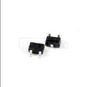
Selecting the appropriate UJT transistor begins with understanding your circuit’s voltage and current requirements. Check the datasheet for maximum interbase voltage, which typically ranges from 20V to 35V for common models—your supply voltage must stay within this limit to prevent damage. Peak point current and valley current specifications determine the RC values you’ll need for stable oscillation, so match these to your intended timing range. The intrinsic standoff ratio affects triggering voltage, with values between 0.56 and 0.75 being most common; higher ratios trigger at higher voltages relative to supply. Package type matters for breadboard prototyping versus permanent installations—TO-92 through-hole packages suit experimenting, while surface-mount options save space in finished products. Temperature stability becomes important for precision timing applications, so review temperature coefficient specifications if your project experiences environmental variations. Cross-reference pin configurations carefully, as some manufacturers reverse B1 and B2 positions compared to standard layouts. For beginners, starting with popular types like 2N2646 or 2N2647 ensures abundant documentation and community support when troubleshooting.
Recommended Suppliers: Spotlight on Utsource and Others
Finding reliable suppliers prevents frustration from counterfeit or damaged components. Utsource offers extensive inventory of UJT transistors alongside complementary parts like NPN transistors and Power MOSFETs such as IRFPG50, allowing hobbyists to source complete projects from one vendor. Their platform provides detailed specifications, datasheets, and inventory transparency that helps verify authenticity before purchasing. Alternative suppliers worth considering include established distributors with hobbyist-friendly minimum order quantities and educational resources. Local electronics shops provide immediate availability and the advantage of inspecting components physically, though selection may be limited. Online marketplaces offer competitive pricing but require extra vigilance regarding seller ratings and return policies. When comparing suppliers, evaluate shipping costs and times against your project deadline, as overnight needs may justify premium pricing. Look for vendors offering small quantity options rather than industrial reels, since hobbyist projects rarely need hundreds of identical components. Customer service responsiveness indicates how well suppliers handle issues like incorrect shipments or technical questions about compatibility.
Ensuring Quality: Verification Steps for Hobbyists
Upon receiving components, immediate inspection catches problems while return windows remain open. Visually examine packaging for damage, moisture exposure, or signs of resealing that suggest counterfeits. Check markings against datasheet specifications—legitimate UJTs display clear manufacturer codes and model numbers, while fakes often show blurred or incorrect printing. Use a multimeter to measure resistance between terminals with the device unpowered; B2 to B1 should show several thousand ohms, while emitter to either base shows diode-like behavior in one direction. Test the intrinsic standoff ratio by building a simple circuit with known good components—if triggering occurs at unexpected voltages, the UJT may be defective or mislabeled. Compare physical dimensions and lead spacing against datasheet drawings, as dimensional discrepancies indicate non-standard parts. Keep purchase records and original packaging until you’ve successfully used components in a working circuit. Join online hobbyist communities where members share experiences with specific suppliers and part numbers, providing crowd-sourced quality intelligence. For critical projects, purchase extras from the same batch to ensure consistency, and consider buying one sample to test before ordering larger quantities. Document your verification process with photos and measurements, creating a reference library that speeds future component evaluation and builds confidence in your electronic components sourcing skills.
Expanding Your Electronics Toolkit with UJT Transistors
The UJT transistor remains an invaluable tool for hobbyists seeking elegant solutions to timing, triggering, and oscillation challenges in electronics projects. Its unique negative resistance characteristic and simple three-terminal design deliver functionality that would otherwise require multiple NPN transistors or complex integrated circuits, reducing both cost and board space significantly. While NPN transistors excel at amplification and Power MOSFETs like the IRFPG50 dominate high-power switching applications, the UJT fills a specialized niche where simplicity and reliability matter most—from relaxation oscillators to SCR triggering circuits. Understanding key specifications such as intrinsic standoff ratio and peak point voltage empowers you to select the right component for your specific application, while sourcing from reliable suppliers ensures you receive authentic electronic components that perform as datasheets promise. The verification steps outlined here protect your investment and project timeline by catching counterfeits early. Now equipped with foundational knowledge and practical guidance, experiment confidently with UJT circuits in your next build, whether creating LED flashers, tone generators, or precision timing applications. Explore manufacturer datasheets, join hobbyist forums, and continue expanding your understanding of how this elegant component can simplify your designs while delivering dependable performance.